Why Insulated Busbar Fails at the Edge: Powder Coat vs. Epoxy vs. Heat Shrink vs. Overmolding
Summary
Busbar insulation lets switchgear and UPS designers pack phases closer together, but only if the coating stays intact everywhere, including the edges. That’s where most coatings are thinnest. Powder and epoxy pull back from sharp corners as they flow and cure, and the electric field is strongest at those same corners. A busbar can measure to spec on every flat face and still fall short where it counts. Thermal cycling adds a slower risk, loosening the bond between copper and coating a little more with every load cycle. Learn how powder coat, epoxy dip, heat shrink, and overmolding compare, how much edge radius a coating needs, and what a complete insulation specification should include.
KEY TAKEAWAYS
ARTICLE
If you’ve ever painted a piece of furniture, you’ve seen this happen. The paint goes on smooth across the flat top and thins out along every edge.
Busbar coatings do the same thing, and on a busbar it matters a lot more. Those edges are where the electric field is strongest, so the insulation ends up thinnest exactly where it has the hardest job.
Most drawings never account for that. They call out a material and a thickness, the bar passes its dielectric test at the factory, and the weak spot stays hidden for years.
What Busbar Insulation Does in Switchgear and UPS
Insulated busbar does three jobs. A properly designed and qualified insulation system can allow phases to run closer together than bare copper, helping high-current switchgear and UPS assemblies fit into compact cabinets. It limits the damage when a dropped tool or loose fastener bridges phases during service. And it keeps moisture, dust, and conductive contamination off the conductor.
The first job is why edge coverage matters so much. Once phases are spaced on the assumption that the bars are insulated, a thin coating at a corner cuts into the clearance the design depends on.
Powder Coat vs. Epoxy Dip vs. Heat Shrink vs. Overmolding
Here’s how the four methods compare on process, thickness, temperature, edge coverage, and cost. Dielectric ratings tend to land close together. The bigger differences show up at the edges, in adhesion, and in what each method costs to tool and repair.
| Powder Coat | Epoxy Dip | Heat Shrink | Overmolding | |
|---|---|---|---|---|
| Process | Electrostatic powder, then cure | Fluidized bed or dip, then cure | Extruded sleeve, shrunk on | Injection or transfer mold |
| Typical thickness | 0.25 to 0.75 mm | 0.5 to 1.5 mm | 0.5 to 2.0 mm wall | 1.5 to 4.0 mm |
| Dielectric strength | Good | Good to excellent | Good | Excellent |
| Temperature rating | Depends on resin. Commonly 105-155 °C class | Commonly 130-180 °C class | Commonly 105-135 °C class | Depends on compound, can exceed 180 °C |
| Edge coverage | Poor without radius, thins at corners | Better than powder, still thins | Excellent, conforms mechanically | Excellent, cavity is filled |
| Adhesion behavior | Bonded, can debond under cycling | Bonded, generally better than powder | Not bonded, mechanical grip only | Bonded or captured, depending on design |
| Complex geometry | Good | Good | Poor, straight runs and simple bends | Excellent, any shape the tool allows |
| Tooling and lead time | None, short setup | None, short setup | None, very short setup | Mold required, 10 to 18 weeks |
| Relative unit cost | Lowest | Low to moderate | Low | Highest, falls with volume |
| Repairability | Difficult | Difficult | Easy, cut and replace | Not repairable |
| Best fit | Volume bars, simple shapes, cost driven | Higher dielectric duty, complex shapes | Straight runs, retrofit, field service | Laminated stacks, complex assemblies, high volume |
Why Insulated Busbar Fails at the Edge
The electric field around a busbar concentrates wherever the surface curves sharply. On a rectangular bar, that means the four long edges carry the highest field on the whole conductor.
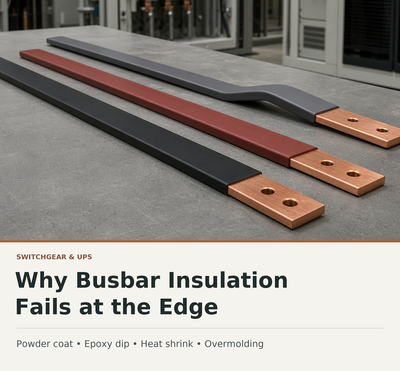
Powder coat and epoxy both flow before they cure, and surface tension pulls them away from each corner toward the flat faces. The coating ends up thinnest right at the edge, and you can’t see it without cutting a part open.
How Much Edge Radius a Coating Needs
| Edge Radius on the Bar | Typical Coverage at the Edge | Practical Consequence |
|---|---|---|
| Sharp, as-sheared | 20% to 40% of flat thickness | Well under spec exactly where field is highest |
| 0.5 mm radius | 40% to 60% of flat thickness | Still a weak point |
| 1.0 mm radius | 60% to 80% of flat thickness | Acceptable for many applications |
| 1.5 to 2.0 mm radius | 80% to 95% of flat thickness | Behaves close to nominal |
| Full radius, r = t/2 | Approaching 100% | No corner for the coating to pull away from |
Edge-coverage percentages are illustrative. Actual results depend on the insulation material, application process, and busbar geometry. Verify these ranges with the coating supplier.
Rounding the edge does two things. First, it puts the fix on the bar, not in the coating. An edge radius does more for coverage than adding nominal thickness. Second, it shows how little a thickness callout tells you on a sharp-edged bar. The callout measures the flat faces, and the flat faces were never the problem.
Why a Deburring Note Isn’t Enough
A punched or stamped bar doesn’t start with a clean corner. The edge has rollover on one face, a fracture zone on the other, and often a leftover burr. The fracture zone is rough and angular, full of tiny local radii.
The coating has to cover an edge that’s both sharp and irregular. Deburring knocks off the burr, but a broken edge isn’t a radiused one. If the bar is going to be insulated, the edge condition is an insulation requirement, and it belongs on the drawing as a dimension with a tolerance.
How Each Method Handles a Corner
Powder coat has the hardest time. The electrostatic charge first pulls powder toward the edges, but flow during cure moves it back off, leaving the corner thin.
Epoxy dip and fluidized bed do better. The coating goes on thicker and resists pulling back, but it still thins at the corner.
Heat shrink avoids the problem. The sleeve wraps the bar mechanically, which is why it often outperforms its dielectric rating on sharp-edged bars and suits retrofits where the bar can’t change.
Overmolding avoids it, too. The mold fills under pressure, so corner thickness is whatever the tool says it is.
Thermal Cycling: The Slow Way Insulation Fails
Dielectric strength gets specified. Adhesion through years of thermal cycling decides whether that dielectric strength is still there in year eight.
Copper and organic coatings expand at different rates, so every load cycle stresses the bond between them. A data center busbar cycles daily with load and seasonally with ambient, which adds up to thousands of cycles.
When a bonded coating separates, it leaves an air gap against the conductor, and in a high-field region, that gap is where partial discharge starts. Powder coat is most dependent on surface prep. Heat shrink grips instead of bonding, so it avoids debonding altogether.
Where thermal cycling is a real concern, specify:
Choosing the Right Insulation Temperature Class
Insulation temperature class usually gets copied from a resin datasheet onto the drawing, and that misses two things.
First, the bar runs hotter than the air around it, and the coating touches the bar. The temperature that matters is the bar’s surface temperature at full load in the hottest expected ambient. On a bar running near its allowable temperature rise, that’s high enough to matter for a Class 105 coating.
Second, a temperature class describes a service life, not a failure point. A Class 105 material at 105 °C is running at the temperature where its rated life was measured. Run it hotter, and that life shrinks on a roughly exponential curve. The question is how long the coating lasts at the temperature the bar reaches.
What a Complete Insulation Specification Includes
A complete specification has seven items. Most busbar drawings carry two.
Masking is where insulation meets the contact surface, and it’s a common source of supplier disagreements because the tolerance is rarely stated. Coating that creeps onto a joint face raises contact resistance. A mask that pulls back too far leaves bare conductor inside a clearance the design assumed was insulated. A few millimeters of variation is normal for a coating process, so where the boundary matters, dimension it and give it a tolerance.
Get the Edge Right Before the Bar Is Coated
MES fabricates, plates, and insulates copper and aluminum busbar for switchgear, busway, and UPS assemblies across eight countries. We specify edge radius on the bar instead of leaving it to the coating line.
Every drawing gets an engineering review before a tool is cut. On an insulated bar, that review usually turns up a coating thickness with no edge requirement behind it.
Send Us Your Insulated Busbar Drawing
Share your drawing, insulation method, and operating temperature. An MES engineer will tell you what your insulation specification is missing.
Frequently Asked Questions About Insulated Busbar
What are the main methods for insulating busbar?
Four methods are common: powder coating, epoxy dip or fluidized bed, heat shrink, and overmolding. All four can reach similar dielectric ratings, but they differ widely in edge coverage, adhesion through thermal cycling, tooling, and cost.
Why does busbar edge radius matter for insulation?
Powder and epoxy coatings pull away from sharp corners as they cure, and the electric field is strongest at those corners. On a sharp, as-sheared edge, coating coverage can drop to 20% to 40% of the flat thickness.
What edge radius should insulated busbar have?
Coverage improves steadily up to about a 1.5 to 2.0 mm radius, where a coating behaves close to its nominal thickness. Specify the radius on the bar drawing as a dimension with a tolerance, not in a deburring note.
Does heat shrink busbar insulation thin at the edges?
Heat shrink avoids the coating pullback that affects powder and liquid coatings. However, sleeve wall thickness can still vary around corners as the material conforms to the bar. That makes heat shrink a strong choice for retrofits where the bar’s edges can’t be changed, provided the finished insulation meets thickness requirements.
What causes partial discharge in insulated busbar?
Partial discharge can occur in air-filled voids or other defects within an insulation system when electrical stress is high enough. Thermal cycling can contribute by weakening the bond between the conductor and its coating, creating air spaces where discharge may develop. Over time, partial discharge can progressively damage the insulation.
Should busbar joint faces be masked during coating?
Yes, with a dimensioned and toleranced mask boundary. Coating on a joint face raises contact resistance, and a mask that pulls back too far leaves bare conductor inside a clearance the design assumed was insulated.