Every Manufactured Part in a Data Center UPS, and How It's Made
Summary
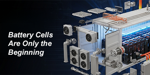
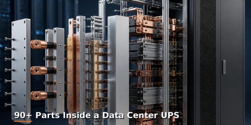
A modular UPS cabinet contains more than ninety manufactured metal parts, across roughly thirty component families, before a single power semiconductor is installed. This article names them, with the process, material and controlling specification behind each. The power electronics are supplied by the OEM. The parts that carry current, remove heat or hold the assembly in alignment are machined, cast, extruded, forged or fabricated.
KEY TAKEAWAYS
ARTICLE
A discussion of a UPS bill of materials usually centers on IGBTs, capacitors, control boards and firmware. Those are the components that carry the manufacturer’s intellectual property.
The same cabinet also contains more than ninety manufactured metal parts. They carry the current the system delivers, remove the heat the modules reject, and hold the assembly in alignment while technicians replace modules over a twenty-year service life.
These parts are individually low in cost and sit on the critical path for both assembly and service. A cabinet can pass its factory acceptance tests and still fail to accept a replacement module later in its life, because the conditions that govern module exchange are not the conditions verified at final test.
The Current Path
Main copper busbars, DC link bus, AC input and output bus, battery busbars, ground bus, forged terminals, bypass bus, die cast insulator supports. Machined C11000 at 100 percent IACS, plated.
The bar itself is a straightforward part; the bolted joint is the controlled feature. A bolted connection conducts through the area in actual metallic contact, which on machined copper is commonly a few percent of the apparent overlap. The controlling specifications are flatness of roughly 0.05 mm, contact pressure of 7 to 10 MPa, and plating measured at the surface where current crosses.
Battery interconnect multiplies the joint count. A resistance rise of 50 microhms at a single joint is negligible. The same rise repeated across several hundred joints in the current path accumulates into a measurable increase in voltage drop and resistive heating. Specify tin at 5 to 15 microns, name the governing standard, and require measurement at the joint face by XRF.
Terminals are forged rather than machined from bar so that grain flow follows the geometry of the part, which improves fatigue behavior under a torqued connection.
Thermal hardware
Heat sinks extruded in 6063-T6 then machined, cooling plates in 6061-T6 or copper, die cast capacitor brackets, baffles, shrouds and fan trays.
Process sequence affects the finished result. An extruded profile leaves the press with bow, and the standard tolerance permits 1.3 mm per meter, so the profile is straightened afterward. Machining the mounting face after straightening is what holds the flatness. If the face is machined first, the straightening operation reintroduces deviation into it. The sequence belongs on the drawing as a process note.
The face carries two specifications together: flatness under the module footprint of approximately 0.05 mm, and surface finish of 0.4 to 0.8 microns Ra. TIM fills roughness at a bond line of 25 to 75 microns and conducts roughly an order of magnitude less heat than the aluminum beneath it. A face that is within flatness but too rough leaves unfilled voids at the interface. A face that is smooth but bowed forces a thicker bond line. Both conditions increase junction temperature, and an inspection that checks profile alone will not detect either.
Module support and retention
Extruded chassis and hot-swap rails, battery tray rails, die cast end plates, capacitor and structural brackets, machined retention hardware.
Engagement has to be repeatable across dozens of insertion cycles, which makes edge condition as important as the primary dimensions. A burr raised during one extraction can create an interference on the next insertion. The symptom seen in the field is a module that will not seat, and the cause is an edge condition that was never called out on the rail drawing.
The corresponding condition on a die cast end plate is harder to detect. Porosity in a load-bearing wall reduces the effective section without changing any external dimension, so the part measures correct and can yield below its expected load. Specify a minimum wall thickness in the loaded region, ASTM E505 Level 2 porosity in that region, and ultrasonic thickness verification per lot. These requirements have to be established at tooling, because they cannot be corrected by downstream inspection.
Enclosure and structure
Roughly forty of the ninety-plus parts. Machined base frame, internal mounting frame, covers and doors, zinc die cast hinges and latches, cable entry plates and trays, control enclosure, sensor mounts, forged lifting lugs and specialty hardware.
Base frame flatness propagates through the assembly. A frame that is out by a millimeter across its length puts every bay above it out of parallel. In service this appears as modules that bind during insertion, while the source of the deviation is the frame rather than the module or the rail.
What modularity costs in metal
A monolithic UPS and a modular UPS contain broadly the same electronics. The difference is mechanical, and it falls on the parts described above: rails that engage repeatably rather than once, retention hardware specified for service cycles rather than for assembly load, a frame flat enough that every bay accepts a module, and an end plate that holds compression for twenty years.
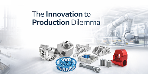
Four processes produce those parts. Sourced separately, that is four qualification cycles, four audits a year and four sets of documentation for one cabinet.
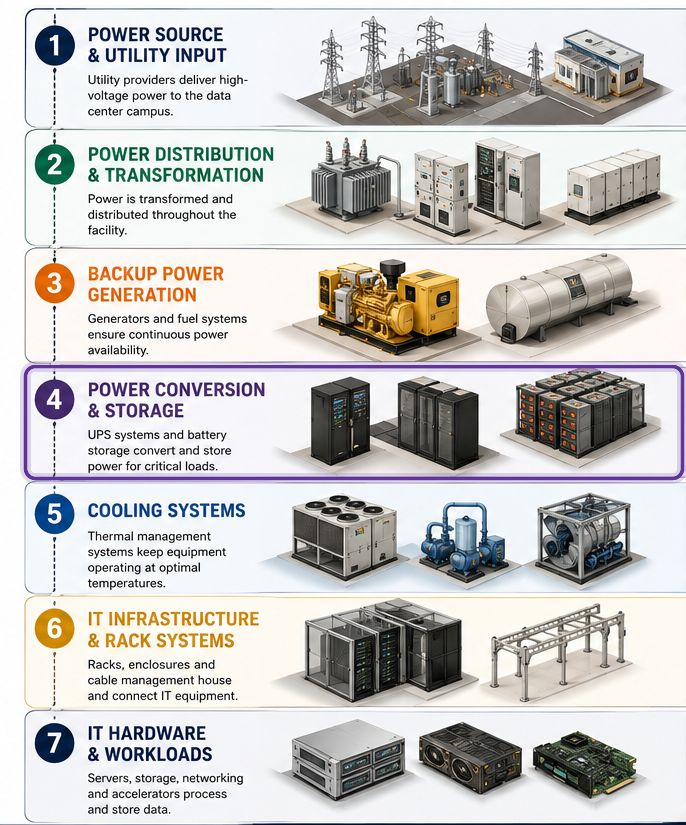
Tier 4 in the seven-tier build
The UPS is one tier of seven between the utility feed and the processor, and the same pattern holds at each: the long-lead assembly gets tracked, and the metal around it often doesn’t. The plating and flatness requirements covered here recur at Tier 2 in switchgear joints and at Tier 5 in direct-to-chip cold plates. Our guide to the 7 tiers of a data center build-out lists the components, processes and controlling specifications at every tier.
Frequently Asked Questions
How many manufactured components are in a data center UPS?
More than ninety metal parts before any electronics are counted, across roughly thirty component families in four groups: the current path, thermal hardware, module support and retention, and enclosure structure. Power semiconductors, DC link capacitors, control boards and firmware come from the OEM.
What material are UPS busbars made from?
C11000 electrolytic tough pitch copper at a minimum of 100 percent IACS, machined and then plated, with tin at 5 to 15 microns or silver at 5 to 13 microns. The thickness has to be specified at the joint face rather than on the flat, because that is the surface carrying current.
Why does IGBT heat sink flatness matter in a UPS?
The module clamps to the base through thermal interface material, which fills microscopic roughness at a bond line of 25 to 75 microns rather than bridging a dimensional gap. Deviation in that face increases junction temperature, and a module can derate in service after passing its assembly checks. Flatness and surface finish have to be specified together.
Why is a heat sink base machined after straightening rather than before?
An extruded profile leaves the press with bow, and the standard tolerance permits 1.3 mm per meter, so the profile is straightened afterward. Machining the mounting face before straightening means the straightening operation reintroduces deviation into the machined face. The sequence belongs on the drawing as a process note.
What fails on a die cast UPS module end plate?
The wall section under sustained compression, rather than the dimensions. Porosity in a load-bearing wall reduces the effective section without producing any change that is measurable externally. Specify a minimum wall in the loaded region, ASTM E505 Level 2 porosity in that region, and ultrasonic thickness verification on a sample per lot.
Related: Every manufactured part in data center switchgear · The 7 tiers of a data center build-out · From 10kW to 100kW: what changes in component design
MES manufactures across all five processes in eight countries and employs engineering and quality staff inside the supplier factories. Every drawing is reviewed before a tool is cut, and CMM verification is performed at source. Send one component from this list and we will identify which specifications can be held as drawn and which cannot.