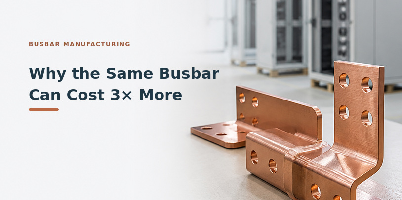
Why the Same Busbar Can Cost 3× More: A Manufacturing Process Comparison
CNC punch and bend, stamping, machining, or extrusion? The manufacturing process can make a 3-fold difference in busbar pricing. Here’s how to evaluate cost, production volume, tolerances, and edge quality before requesting a quote.
Busbar Manufacturing for High-Density Data Centers: Which Process Makes Sense?
Summary
CNC punch and bend, stamping, machining, and extrusion can all produce busbar for high-density data centers, but the same drawing can produce quotes 3 times apart depending on which process a supplier assumes. The right process depends on annual volume, tooling investment, design stability, critical tolerances, and edge quality. This post compares the 4 processes and shows what to put on a busbar drawing and RFQ. Machining often costs least below about 200 pieces a year. CNC punch and bend usually leads from about 200 to 5,000. Stamping becomes competitive above roughly 10,000. Joint flatness and hole position deserve tight control, while most other features don’t. Insulated busbar needs a specified edge radius, and current-carrying extrusions need 6101 alloy.
KEY TAKEAWAYS
ARTICLE
At first glance, a busbar doesn’t look particularly complicated. A flat piece of copper, a few holes, maybe a couple of bends. So why can the same drawing generate quotes that differ by as much as 3×?
MES has seen it firsthand. The same busbar drawing goes to multiple suppliers, and the quotes come back dramatically different. Material costs and supplier margins don’t explain the gap. One supplier assumes CNC punch and bend, while another prices stamping or machining, and each process carries different economics.
Unless those assumptions are clear, the quotes can’t be compared on equal terms.
Data centers raise the stakes. A liquid-cooled AI rack can draw around 120 kW. At the 48 to 54 V DC used inside many of these racks, that’s well over 2,000 amps. Managing that much current makes busbar a critical part of power distribution, both inside the rack and in the switchgear and busway that feed it.
For data center engineers and sourcing teams, the challenge is choosing a manufacturing process that delivers the required performance at the right cost. That starts with understanding how CNC punch and bend, stamping, machining, and extrusion compare.
4 Busbar Manufacturing Processes: Which Fits Your Project?
Each manufacturing method has advantages, but the best choice depends on production volume, part geometry, tolerance requirements, and how likely the design is to change.
| Manufacturing Process | Best Fit | Key Tradeoff |
|---|---|---|
| CNC Punch and Bend | Low- to mid-volume production, roughly 200–5,000 pieces annually | Flexible, with no dedicated tooling, but processing costs increase with complexity. |
| Stamping | High-volume production, typically above 10,000 pieces annually | Fast production and lower unit costs, but requires upfront tooling investment and makes design changes more expensive. |
| CNC Machining | Low-volume or precision-critical parts | Excellent tolerances and edge quality, but machining time becomes costly at higher volumes. |
| Extrusion | Long aluminum busbars with constant cross-sections | Efficient for long, constant profiles, but requires an extrusion die and limits cross-sectional design flexibility. |
The volume ranges are starting points, not hard rules. A complex busbar with demanding edge requirements may need machining regardless of volume, while a stable design can justify stamping sooner than expected.
When Does Stamping Cost Less Than CNC Punching?
A manufacturing process that makes financial sense for 200 busbars may be the wrong choice at 10,000. The difference comes down to tooling investment, production time, and how many parts share those costs.
As a guideline:
But volume alone doesn’t determine the best process.
Every additional hole increases CNC punching time. On a stamped part, more features add tool cost but little cycle time. Thicker material takes longer to punch. And multiple part variations change the math: 10 similar busbars at 1,000 pieces each may be economical with CNC programming changes, while stamping could require ten separate tools.
Design stability matters, too. Moving a hole on a CNC-punched busbar may require only a programming change. Making the same adjustment to a stamped part can mean modifying a hard tool, potentially adding weeks.
The right calculation accounts for expected production volume, tooling costs, processing time, and the likelihood of engineering changes before committing to a manufacturing route.
Busbar Tolerances: Tighten the Joints, Not the Whole Part
Tighter tolerances usually mean higher manufacturing costs. But not every dimension on a busbar needs the same level of precision.
The most critical tolerances are typically at electrical joints, where contact surfaces and bolt alignment affect fit and connection quality.
Typical busbar tolerances include:
These are illustrative values, not universal specifications. Actual tolerances depend on the joint design and application.
Applying a tight tolerance across an entire busbar can force a switch from CNC punch and bend to more expensive machining without improving electrical performance.
Specify precision where the connection requires it and allow standard tolerances elsewhere. That gives suppliers more manufacturing options without compromising the joint.
A Smooth Edge Isn't Necessarily a Good Edge
A punched or stamped busbar can look smooth after deburring, but its edge condition can still affect insulation performance and bend integrity.
When a punch cuts through copper, it deforms the metal until it fractures. The resulting edge has 4 zones: rollover at entry, a smooth burnished band, a rougher fracture zone, and a burr at exit. The metal alongside the cut also becomes work-hardened.
Deburring removes the burr, but it doesn’t eliminate the other edge features or reverse the work hardening.
For insulated busbar, specify an edge radius rather than relying on a general deburring note. Powder and epoxy coatings can thin at sharp edges during application and curing. Those edges also concentrate electric fields, making adequate insulation coverage especially important. A defined radius provides a more consistent surface for coating.
For busbar with bends near punched edges, review the bend location and edge condition. Work-hardened material is less ductile and more susceptible to cracking during forming. Moving the bend farther from the punched edge or adjusting the manufacturing process may reduce that risk.
“Edge radius is one of the most common gaps we see on insulated busbar drawings,” says Brad Layne, Engineering Manager at MES. “If it isn’t specified, the edge condition depends on the process the supplier chooses. Putting a radius on the drawing keeps coating performance consistent no matter who makes the part.”
Before releasing the drawing for quotation, identify edges that need controlled geometry and specify the required radius. A general “deburr all edges” note isn’t enough.
Extruded Busbar: Why the Aluminum Alloy Matters
Extrusion is a practical option for long aluminum busbars with a constant cross-section. The process produces a continuous profile that’s cut to length and machined where connections or mounting features are needed.
For current-carrying busbar, alloy selection matters. Two aluminum alloys may look interchangeable on a purchase order but have different electrical conductivity requirements.
6101 aluminum is designed for electrical conductor applications and is available with minimum conductivity requirements under ASTM B317.
6063 aluminum is commonly used for structural extrusions. It has lower electrical conductivity and isn’t specified to the same electrical conductor requirements.
Substituting 6063 for 6101 without evaluating the electrical design could increase resistance and heat generation.
Specify the required alloy, temper, and minimum conductivity on both the drawing and purchase order.
What to Include in Your Busbar Drawing and RFQ
A complete busbar drawing helps suppliers quote the same requirements instead of making their own assumptions about materials, tolerances, and manufacturing methods.
Before sending a drawing out for quotation, make sure it identifies:
The more clearly these requirements are defined, the easier it is to compare quotes, evaluate manufacturing options, and avoid unexpected costs after tooling begins.
Get the Manufacturing Process Right Before Tooling Begins
The lowest busbar quote isn’t always the best value. A process that looks economical at one production volume may become expensive when designs change, tolerances tighten, or specialized finishing is required.
MES supplies copper and aluminum busbar through a manufacturing network spanning 8 countries, with capabilities in CNC punch and bend, stamping, machining, and extrusion.
Our engineering team reviews drawings before tooling begins, looking at critical tolerances, edge requirements, production volumes, and material specifications. That review helps identify the most practical manufacturing route upfront.
Have a busbar drawing ready for review? Talk to an MES engineer about manufacturing options and pricing.
Frequently Asked Questions About Busbar Manufacturing
Which manufacturing process is best for low-volume busbar production?
CNC machining is often the most economical option below about 200 pieces a year, especially when precision edges are required. As volumes increase, CNC punch and bend usually offers better economics because it uses standard tooling and flexible programming.
When should busbar be stamped instead of CNC punched?
Stamping typically becomes competitive around 10,000 pieces a year. The breakpoint moves with part complexity, number of variants, and design stability. Between about 5,000 and 10,000 pieces, a design change on a stamped part means a tool modification that can take weeks, compared with a programming change on a CNC-punched part.
Does deburring make a sheared busbar edge equivalent to a machined one?
No. Deburring removes the burr, but it doesn’t remove the rollover, fracture zone, or work-hardened material, and it doesn’t change the edge profile. If edge condition matters, the drawing should specify an edge radius.
What should engineers specify for insulated busbar edges?
Specify the required edge radius rather than relying on a general deburring note. Powder and epoxy coatings can thin at sharp edges, and those edges concentrate electric fields. A defined radius gives the coating a more consistent surface to cover.
What tolerances does busbar need?
Tight tolerances are usually needed only at electrical joints: about 0.05 mm flatness across the bolted contact area and about ±0.10 mm hole position on critical bolt patterns. Overall length, clearance holes, and non-functional edges typically hold ±0.25 mm. Applying a tight tolerance across the whole part can push it toward machining without improving the connection.
What aluminum alloy should be used for extruded busbar?
6101 aluminum is the electrical conductor alloy, available with minimum conductivity requirements under ASTM B317. 6063 is a structural alloy with lower conductivity and no conductivity requirement. For current-carrying busbar, specify 6101, the required temper, and minimum conductivity on the drawing and purchase order.