
The 7 Tiers of a Data Center Build-Out
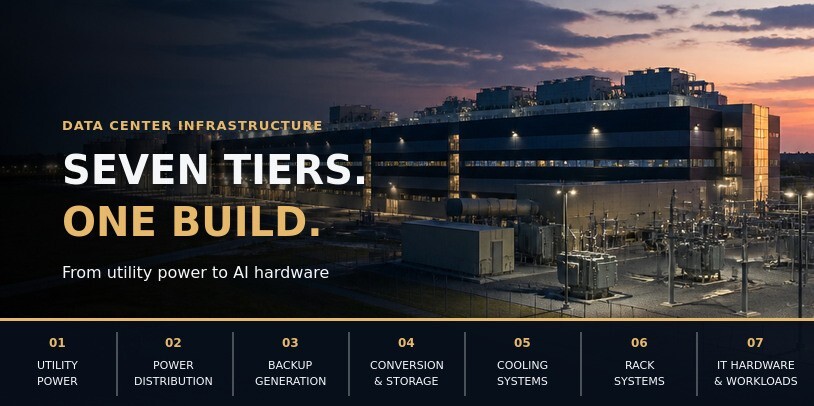
Summary
A hyperscale data center steps utility power down to processor voltage through seven distinct tiers, and every tier is assembled from machined, cast, forged, extruded and fabricated metal. This article walks through all seven tiers, names the components at each layer, identifies the manufacturing process that produces each one, and gives the tolerance or specification that governs whether it performs as intended.
KEY TAKEAWAYS
ARTICLE
Every data center reference architecture shows the same block diagram: utility feed, substation, switchgear, UPS, PDU, rack, cooling. The diagram is accurate at the system level, but it does not identify the individual parts that have to be purchased.
Between those blocks sit several hundred manufactured components, and many of them do not appear on the diagram. Lead time on a 2,500 kVA transformer is tracked as a matter of course. Lead time on the forged lifting lugs that allow a crane to set that transformer on its pad often is not, and the unit cannot be placed until those lugs are available.
What follows is a tier-by-tier component list, with the manufacturing process used for each part and the specification that governs its performance. The list is intended to be exhaustive rather than selective, and every component named is one MES machines, casts, forges or extrudes.
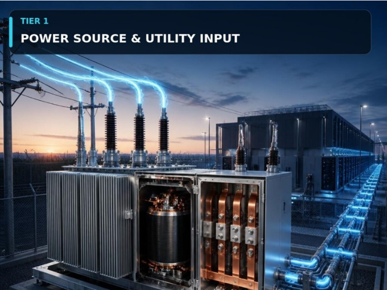
1. Power Source and Utility Input
Utility power arrives at transmission or sub-transmission voltage and is stepped down at an on-site substation. In a large deployment this substation is utility-scale and sits inside the site fence line, using the same classes of hardware found in a distribution substation.
| Component | Process | Specification that matters |
|---|---|---|
| Primary busbar and bus stabs | CNC machined, plated | Joint face flatness 0.05 mm; C11000 at 100% IACS |
| Terminal studs and lugs | Forged then machined | Grain flow follows the load path; certified per heat lot |
| Ground pads and bonding hardware | Forged and machined | UL 467 listed; 95% IACS minimum |
| Transformer turret flanges | Machined from plate | 0.10 mm flatness across a Ø1,200 mm gasket face |
| Bushing wells and terminal studs | CNC machined, plated | Tin 8-20 µm or silver 5-13 µm at the contact face |
| Lifting and jacking lugs | Forged, galvanized | 4:1 design factor; MT or UT inspected per lot |
| Pressure relief valve bodies | High-pressure die cast | Cracks 10-15 psi; pressure tested at source, 100% |
| Radiator fin panels and headers | Extruded, machined | Straightness 0.5 mm/m against a 1.3 mm/m standard |
| Tap changer shafts | Forged, machined | Straightness 0.1 mm per 100 mm; oil-tight seal face |
| Drain and oil valve bodies | Investment cast, machined | CF8M, leak-tight against hot oil for service life |
| Cabinet hardware, hinges, latches | Zinc die cast | 10,000-cycle duty; 0.8 mm minimum wall |
| Structural framing and skid | Extruded, machined | 6005A-T6; carries the seismic case |
The failure mode: bolted joint creep.
Aluminum creeps under sustained bolt load at ambient temperature. On 6101-T6 the practical threshold is approximately 40 to 50 percent of yield, or roughly 70 MPa of bearing stress against a yield strength of 172 MPa. An unsprung aluminum-to-copper joint can lose 30 to 50 percent of its initial preload within the first year. The resulting increase in contact resistance raises local temperature, and the higher temperature increases the rate of creep.
Increasing installed torque does not address this mechanism. Two measures do: a belleville washer sized to maintain 60 to 80 percent of the initial load through the relaxation, and sufficient bearing area to keep contact stress below the creep threshold, which generally requires a washer outside diameter at least twice the bolt diameter.
Not manufactured here: core laminations, windings, bushings, protection relays, instrument transformers.
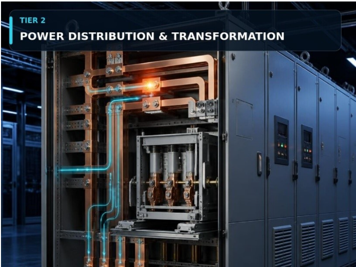
2. Power Distribution and Transformation
Medium-voltage switchgear and unit substations distribute power through the building. A switchgear cabinet contains parts from all five metal-forming processes within a single enclosure. Ratings run from 630 A to 6,300 A at 12 kV to 38 kV, and a cabinet can carry more than 120 manufacturable parts before the vacuum interrupters are installed.
| Component | Process | Specification that matters |
|---|---|---|
| Main copper busbars | Busbar fabrication, machined | Contact pressure 7-10 MPa across the joint area |
| Copper terminals and connectors | Forged then machined | Plated at the joint face, not on the flat |
| Cable termination connectors | Forged and machined | Aluminum joints creep; belleville hardware required |
| Operating mechanism housing | A380 die cast, machined | ±0.05 mm bore to mounting face, 10,000 operations |
| Trip latch and contact carrier | Investment cast 17-4PH H900 | ±0.13 mm on the first 25 mm; high-cycle fatigue |
| Operating shaft | Forged 4140 Q&T, machined | Ø20-60 mm to 900 mm; straightness 0.1 mm/100 mm |
| Secondary disconnects | CNC machined, stamped | Plug-in contact geometry |
| Insulator supports and brackets | Die cast, machined | Creepage and clearance distances |
| Breaker cradle and truck frame | Extruded, machined | Racking alignment through thousands of cycles |
| Base frame and basepan | CNC machined | Flatness carries the cabinet’s alignment |
| Cable entry and gland plates | CNC machined | Sealing and EMI continuity |
| Enclosure framing and panels | Extruded, machined | 6063 and 6005A; 1.2 mm minimum wall |
| Ventilation louvers and screens | Stamped | Airflow versus ingress rating |
| Door hinges, handles, latches | Zinc die cast | Cycle-rated and corrosion-rated |
| Wiring duct and harness tray | Extruded, stamped | Separation and strain relief |
| Ground busbar | Busbar fabrication | UL 467; bonding continuity |
| Arc chute assembly | Sheet metal, CNC | Interruption path geometry |
| Lifting lugs | Forged | Certified per heat lot |
The failure mode: joint contact area.
Thermal scanning of a busbar system under load shows the highest temperatures at the bolted joints rather than at mid-span. Actual metallic contact on a bolted copper joint is commonly a few percent of the apparent overlap area, because machined faces meet at asperity peaks and current constricts through those points. Four specifications control the result: flatness at the joint face, surface finish of 1.6 to 3.2 µm Ra, contact pressure, and plating thickness. All four are frequently omitted from the component drawing.
Not manufactured here: vacuum interrupters, protection relays, instrument transformers, composite and ceramic bushings.
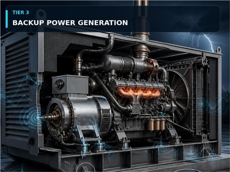
3. Backup Power Generation
Standby generators carry the facility when utility power is unavailable for longer than the batteries can bridge. On a hyperscale campus, installed standby capacity is measured in tens of megawatts. The engine and alternator are supplied by the generator OEM. The structural and mounting hardware around them is manufactured to print.
| Component | Process | Specification that matters |
|---|---|---|
| Alternator end brackets | Cast and CNC machined | ±0.05 mm on bearing seats |
| Engine mounting brackets | Cast and machined | Weld toe geometry governs fatigue, not base metal grade |
| Isolator mounting plates | Machined, stamped | Vibration isolation interface |
| Exhaust manifold flanges | Investment cast, machined | CF8M or 310S; service to 850 °C |
| Turbocharger mounting brackets | Investment cast, machined | Thermal cycling at the hot end |
| Radiator coil frames and end plates | Extruded, machined | Coil retention and header support |
| Fan shrouds and blower housings | A380 die cast | 1.5 mm minimum wall |
| Canopy and acoustic framing | Extruded | Outdoor finish specified with the alloy |
| Fuel system brackets and plates | Machined, stamped | Certified for fuel service |
| Control panel enclosures | Die cast, machined | IP-rated sealing |
| Base rails and skid | Structural extrusion, welded | Distortion control across a long weldment |
| Lifting lugs | Forged | 4:1 design factor |
The failure mode: weld fatigue at the toe.
Changing a mounting bracket from S235 to S355 increases static yield strength by roughly 50 percent but produces little change in fatigue life, because a fillet-welded joint initiates failure at the weld toe rather than in the base metal. In the fatigue classification systems associated with AWS D1.1, an as-welded transverse fillet is rated near FAT 80 irrespective of base metal grade. Toe dressing raises the classification toward FAT 112, an increase of roughly 30 percent in allowable stress range.
Whether the bracket accumulates those cycles depends on resonance. An 1800 rpm genset has a firing frequency near 30 Hz, and a structure with a first mode below 60 to 70 Hz falls within the excitation band.
Not manufactured here: engines, alternators, turbochargers, hot-section turbine components, controls.
4. Power Conversion and Storage
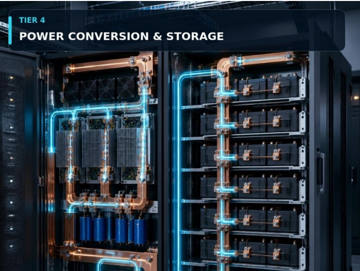
UPS systems condition power continuously and bridge the seconds between utility failure and generator start. Battery cabinets provide the ride-through. A modular UPS carries more than 90 manufacturable components, and each module is a dense assembly of power electronics producing significant waste heat.
| Component | Process | Specification that matters |
|---|---|---|
| Main and battery busbars | Busbar fabrication, plated | 200-600 bolted joints per cabinet; tin 5-15 µm |
| Input and output terminals | Forged and machined | Load and supply terminations |
| Power module heat sinks | Extruded then machined | 0.05 mm flatness, 0.8 µm Ra under the module |
| Cooling plates and heat spreaders | CNC machined | 0.10 mm flatness against the module face |
| Capacitor mounting brackets | A380 die cast, machined | DC link capacitor retention |
| Battery tray rails | Extruded and machined | Module support and extraction |
| Module end plates | A380 die cast, machined | 5 mm minimum wall in the loaded region |
| Module retention hardware | CNC, stamped | Hot-swap repeatability over 50 cycles |
| Structural support brackets | Die cast, CNC | Frame rigidity under seismic load |
| Base frame and internal frame | CNC machined, sheet + CNC | Module bay alignment |
| Cable entry plates | CNC machined | Bottom or top entry, sealed |
| Cable management trays | Sheet metal, extruded | Routing and separation |
| Fan and blower mounting brackets | Die cast | Forced-air routing across modules |
| Insulator supports | Die cast | Creepage between phases |
| Ground busbar | Busbar fabrication | Bonding across modules |
| Doors, hinges, latches | Sheet metal, zinc die cast | Access and cycle life |
| Lifting lugs | Forged | Cabinet handling |
The failure mode:interconnect plating across hundreds of joints.
A battery cabinet contains 200 to 600 bolted connections, and each one conducts through its plating rather than through the base metal. A resistance rise of 50 microhms at a single joint is negligible. The same rise repeated across several hundred joints in the current path accumulates into a measurable increase in voltage drop and resistive heating. The specification is tin at 5 to 15 µm, measured at the joint face by XRF rather than on the flat.
On the structural side, porosity in a compression-loaded die cast end plate reduces the effective load-bearing wall section without producing any change that is detectable from outside the part. The applicable requirement is ASTM E505 Level 2 in loaded areas, verified by ultrasonic thickness measurement on a sample from each lot.
Not manufactured here: cells, battery management systems, power semiconductors, control boards, firmware, fire suppression.
5. Cooling Systems
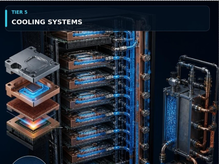
A conventional server rack dissipates five to ten kilowatts, which forced-air cooling can remove. An AI training rack dissipates several times that, and above a certain density no fan arrangement moves sufficient air through the cabinet. Cooling has therefore moved from the room to the rack, and then to the processor, which introduced a new class of precision machined component.
| Component | Process | Specification that matters |
|---|---|---|
| Cold plate base | CNC machined C11000 | 0.025 mm flatness across the die footprint |
| Skived fin array | Skived from solid base | 0.2-0.6 mm fins at 0.3-1.2 mm pitch; no fin-to-base joint |
| Cold plate cover | Machined, brazed or welded | Braze void under 10 percent of joint area |
| Port fittings and bosses | CNC machined | Brass or 316; 1/8 in to 1 in thread |
| Quick-disconnect bodies | CNC machined | Dripless, 500-cycle rated |
| CDU manifold bodies | CNC machined | 6061-T6 or 316; up to 900 × 400 × 200 mm |
| Distribution headers | Extruded and machined | To 6 m, straightened 0.5 mm/m |
| Rack manifold bodies | Extruded, CNC machined | Full rack height, blind-mate couplings |
| Pump volutes and housings | Investment cast, machined | ±0.13 mm on the first 25 mm |
| Heat exchanger end plates | CNC machined | Plate stack retention |
| Valve and sensor bosses | CNC machined | Instrumentation and isolation ports |
| Filter housings | Machined or die cast | Serviceable element |
| Extruded heat sinks | Extrusion + CNC | High aspect ratio fin arrays |
| Fan shrouds and blower housings | A380 die cast | Airflow management |
| Coil frames and end plates | Extruded, machined | Coil retention |
| Condensate pans | Formed, machined | Corrosion-resistant drainage |
| Immersion tank structures | Extruded, welded | Dielectric fluid containment |
| Rear-door frames and coil headers | Extruded, machined | Retrofit onto existing racks |
The failure mode:flatness, and the gap you cannot see.
A cold plate that sits proud of the die by 0.04 mm leaves a gap that the thermal interface material has to fill. TIM conductivity is a few W/m·K, against 388 W/m·K for copper, so a plate can meet its dimensional inspection and the processor can still throttle. Flatness therefore has to be called out across the contact footprint rather than as a general profile tolerance, because a plate can hold 0.10 mm profile and still be dished 0.04 mm over the die.
Surface finish is the paired specification, at 0.4 to 0.8 µm Ra. TIM is intended to fill microscopic surface roughness at a bond line of 25 to 75 µm; it is not intended to bridge a dimensional gap. Excess roughness and excess bow both increase junction temperature, so the two specifications have to be held together.
Not manufactured here: thermal interface material, pumps, heat exchanger plate stacks, dielectric fluid, controls.
6. IT Infrastructure and Rack Systems
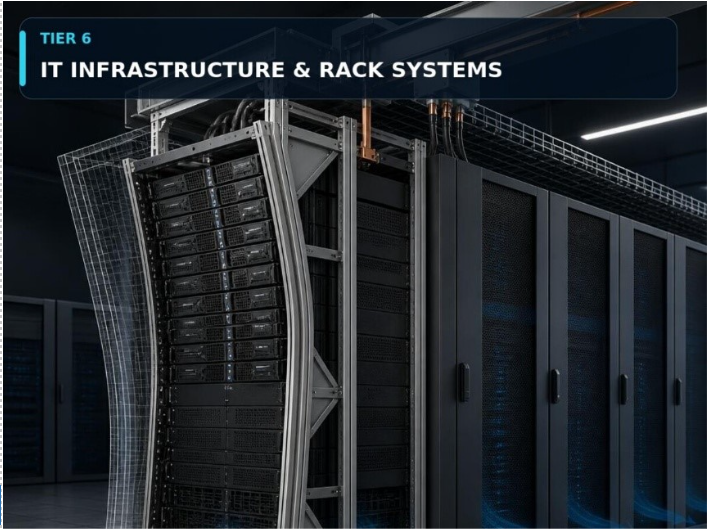
Racks, enclosures and cable management hold the IT equipment and route power and coolant to it. Legacy halls loaded 1,000 to 1,500 pounds per rack. AI deployments run 3,000 to 5,000 pounds per rack, with the mass concentrated toward the top of the frame and distributed unevenly. That loading condition governs the frame design more than total mass does.
| Component | Process | Specification that matters |
|---|---|---|
| Rack frames and mounting rails | Extruded, machined | ±0.4 mm cumulative U-position over 42U |
| Structural brackets and gussets | Die cast, stamped | Torsional stiffness under asymmetric load |
| Base frames and leveling feet | Machined, cast | Floor loading and alignment |
| Seismic anchors and base hardware | Forged, machined | Zone 4 restraint |
| Cable management arms and trays | Extruded, stamped | Routing, strain relief, separation |
| Blanking panels and airflow seals | Stamped | Hot and cold aisle containment |
| Busway housing sections | Extruded, machined | Conductor enclosure and mechanical protection |
| Busway conductor bars | CNC machined, extruded | 6101-T6 at 55-57% IACS, not 6063 |
| Joint blocks and splice plates | Machined | Flatness specified at the joint |
| Bus stabs and plug-in contacts | Machined, plated | Silver 5-13 µm, tin 5-15 µm |
| Tap-off box housings | A380 die cast, machined | Branch circuit enclosure |
| Rack PDU bodies | Extruded | Straightness over a 2,200 mm body |
| Breaker mounting pans | Die cast, machined | ±0.10 mm hole position |
| Hanger and seismic brackets | Stamped, machined | Overhead suspension |
| Door frames, hinges, locks | Zinc die cast | Access control and cycle life |
The failure mode:deflection under asymmetric load.
A frame qualified against a uniform static load can fail under a top-weighted asymmetric load of the same total mass. The specification that identifies this is a deflection limit rather than a load rating: L/240 on a mounting rail, or 5 to 6 mm over a 42U span. A load rating establishes only that the frame did not collapse. A deflection limit establishes whether equipment can be mounted without shimming. U-position accuracy is the second specification: ±0.4 mm cumulative over 1,867 mm. Standard extrusion straightness of 1.3 mm per meter consumes that tolerance budget on its own, which is why precision straightening to 0.5 mm/m has to be specified before the die is cut.
Surface finish is the paired specification, at 0.4 to 0.8 µm Ra. TIM is intended to fill microscopic surface roughness at a bond line of 25 to 75 µm; it is not intended to bridge a dimensional gap. Excess roughness and excess bow both increase junction temperature, so the two specifications have to be held together.
Not manufactured here: breakers, meters, monitoring hardware, PDU electronics, network equipment.
7. IT Hardware and Workloads
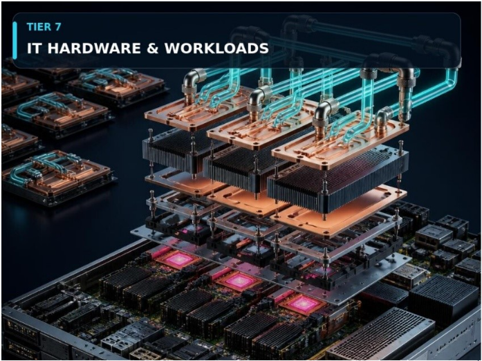
Servers, storage, networking equipment and accelerators generate the heat that the preceding six tiers exist to supply and remove. MES does not build servers. It does manufacture thermal and structural components used inside them, and this is the fastest-changing component family in the facility.
| Component | Process | Specification that matters |
|---|---|---|
| Direct-to-chip cold plates | CNC machined, skived | One to eight per server; 0.025 mm flatness |
| Cold plate mounting hardware | Machined, stamped | Socket load distribution across the die |
| Backplates and retention frames | Machined, stamped | Backplate flex moves load off the die center |
| Extruded heat sinks | Extrusion + CNC | Memory, VRM and secondary components |
| Machined heat sink bases | Extruded then machined | 0.05 mm flatness under the module |
| Chassis and structural parts | Stamped, machined, extruded | Rigidity in a 1U to 4U envelope |
| Precision CNC components | CNC machined | Tight-tolerance mounting and alignment |
| Nickel plating on copper | Sourced | 3-8 µm; oxidation barrier in glycol loops |
The failure mode:flatness drift across the lot.
A cold plate that holds 0.025 mm flatness at first article and 0.06 mm by the four-hundredth part will pass incoming inspection and still reduce thermal performance in service. Flatness verified per lot, on the parts that ship, is a different requirement from flatness verified once at first article, and it governs whether an accelerator sustains its rated clock speed over the life of the installation.
Not manufactured here: processors, memory, storage, networking silicon, PCBs, thermal interface material.
What the Seven Tiers Have in Common
Copper appears in five of the seven tiers: busbar at Tier 1, conductors and terminals at Tier 2, interconnect at Tier 4, cold plates at Tier 5, and bus stabs at Tier 6. That concentration has a commercial consequence. Since April 2026, Section 232 duty on covered copper articles is assessed on the full customs value of the imported part rather than on its copper content, so a machined and plated part carries duty on the machining as well as on the metal.
Five processes cover the great majority of the build, and most assemblies need three or more.
| Process | Appears in tiers | Representative components |
| CNC machining | 1, 2, 4, 5, 6, 7 | Busbar, cold plates, manifolds, base frames, heat sink bases |
| High-pressure die casting | 1, 2, 3, 4, 5, 6 | Mechanism housings, relief valves, end plates, tap-off boxes |
| Investment casting | 1, 2, 3, 5 | Trip latches, valve bodies, pump volutes, exhaust flanges |
| Forging | 1, 2, 3, 4, 6 | Lifting lugs, operating shafts, terminals, seismic anchors |
| Aluminum extrusion | All seven | Radiator panels, framing, busway housings, heat sinks, rails |
A single medium-voltage switchgear cabinet requires all five processes. Sourced separately, that is five qualification cycles, five audits, five PPAP submissions and five sets of material certificates arriving in five different formats, with first shipment set by the slowest of the five rather than by their average.
This returns to the point made at the outset. Sourcing attention generally follows spend: a core assembly is assigned a sourcing owner, a dual-source plan and a quarterly review, while a low-cost bracket is handled by purchase order. That allocation is defensible on cost and less effective on schedule, because the constrained long-lead items are already monitored while the low-value parts are not.
Related: The 90+ components in a data center UPS · Why BESS depends on more than battery cells · The transformer shortage isn’t really a transformer shortage.
MES manufactures across all five processes in eight countries and employs engineering and quality staff inside the supplier factories. We have moved roughly 240 tools since 2023 and have held ISO 9001 certification since 2009. Send a drawing from any tier on this list and we will identify which specifications can be held as drawn and which cannot. Quotes take three to five business days, and manufacturability feedback takes five.
Talk to us about a component on your drawing.
Frequently Asked Questions
How many manufactured components are in a data center?
Across the seven tiers, several hundred distinct metal parts before any electronics are counted. A medium-voltage switchgear cabinet alone carries more than 120 manufacturable components and a modular UPS more than 90. Those figures exclude cells, semiconductors, interrupters and controls, which come from specialty OEMs.
What are the seven tiers of a data center build-out?
Power source and utility input; power distribution and transformation; backup power generation; power conversion and storage; cooling systems; IT infrastructure and rack systems; and IT hardware and workloads.
Which manufacturing processes does a data center build require?
Five metal-forming processes cover the great majority: CNC machining, high-pressure die casting, investment casting, forging and aluminum extrusion. Aluminum extrusion appears in all seven tiers, CNC machining in six.
What is the most demanding machined component in a data center?
The direct-to-chip cold plate. Flatness across the die footprint is held to 0.025 mm, skived fins run 0.2 to 0.6 mm thick at 0.3 to 1.2 mm pitch, and the brazed cover forms a pressure boundary over energized hardware.
Why did copper component costs change in 2026?
Section 232 duty on covered copper articles moved from being assessed on metal content to the full customs value of the imported part. Machined and plated copper carries substantial processing value beyond the raw metal, so the dutiable base grew considerably.
Notes for the developer
What maps to what
The only new element: tables
Seven component tables, three columns each, 106 rows total. The existing blog template has no table style. If adding one is a problem, the fallback is a definition list per tier — component name in bold, then process and specification as body text beneath. That reads acceptably but roughly doubles the section length.
Recommend adding a simple table style. It will be reused across the whole 51-post program, and component tables are the format that makes these posts citable.
Length
Roughly 3,900 words against the usual 1,200. This is the hub post that the other fifty link back to, and an answer engine asked what a data center needs manufactured should find one source covering all seven tiers rather than seven partial ones. If the template caps read time, 14 min is accurate.


